Inductive Reactive Power: The Formula and How to Use It
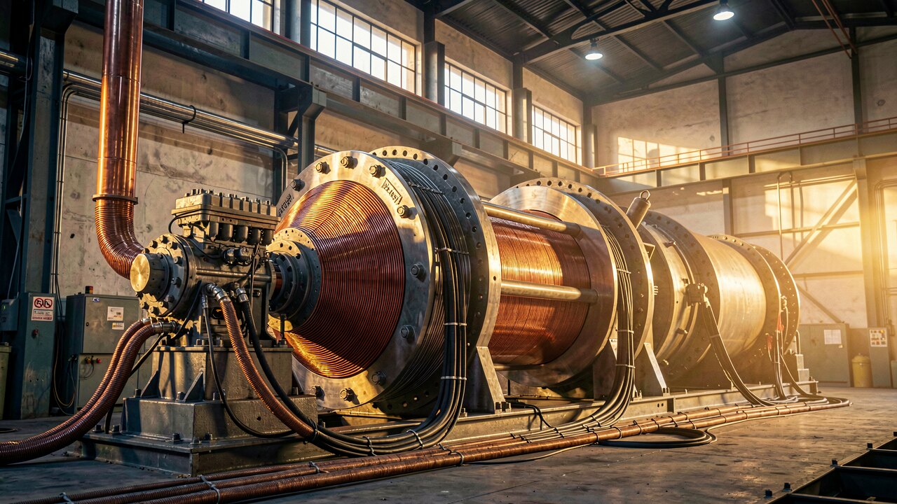
Inductive reactive power Q is the power that oscillates between the source and inductive loads like motors and transformers without doing useful work. The core formula is Q = U · I · sin(φ), measured in var (volt-amperes reactive).
Inductive reactive power is Q = U · I · sin(φ), where U is the RMS voltage, I is the RMS current, and φ is the phase angle between them. For a purely inductive load the current lags the voltage by 90°, so sin(φ) = 1 and Q = U · I. The unit is var (or kvar for thousands). Q is called 'inductive' when the current lags the voltage, which is the typical case for coils, motors and transformers.
If you know the current and the inductive reactance X_L, use Q = I² · X_L. The reactance itself comes from X_L = 2π · f · L = ω · L, where f is the frequency (50 Hz in Europe) and L is the inductance in henry. Equivalently, if voltage across the inductor is known, Q = U² / X_L. These forms are useful when the load is specified by its inductance rather than its phase angle.

Reactive power is one side of the power triangle: S² = P² + Q². So if you already know apparent power S and active power P, you get Q = √(S² − P²). You can also write Q = P · tan(φ). The active power is P = U · I · cos(φ), and cos(φ) is the power factor — so a lower power factor means a larger reactive share for the same active load.
Take a single-phase load at U = 230 V drawing I = 10 A with a power factor cos(φ) = 0.8. The phase angle is φ = arccos(0.8) = 36.87°, so sin(φ) = 0.6. Then Q = 230 · 10 · 0.6 = 1380 var ≈ 1.38 kvar (inductive). Cross-check: S = 230 · 10 = 2300 VA, P = 2300 · 0.8 = 1840 W, and √(2300² − 1840²) = 1380 var — the same result.
For a balanced three-phase load the formula becomes Q = √3 · U_L · I_L · sin(φ), where U_L is the line-to-line voltage and I_L the line current. The √3 factor accounts for the three phases. The same power-triangle relation Q = √(S² − P²) still holds, with S = √3 · U_L · I_L.
Inductive reactive power loads cables and transformers with current that does no useful work, and many grid operators bill a reactive-power component when the power factor is poor. A poor cos(φ) at a generator's grid feed-in point can lead to grid charges. Capacitor banks or controlled compensation offset the inductive Q, raising the power factor toward 1 and cutting those losses and fees.