Kompensationsanlage Planung: How to Plan a Power Factor Correction System

Planning a compensation system (Kompensationsanlage) means measuring your actual reactive power demand, calculating the kvar you need to reach a target power factor, and then choosing a design that survives the harmonics on your network. The work splits into five steps: load measurement, kvar sizing, harmonic assessment, step and switching design, and installation planning.
1) Measure. Record active power (kW), reactive power (kvar) and power factor at the point of common coupling over a period that covers a full operating cycle — typically at least one working week, longer for seasonal loads. 2) Size. Calculate the capacitor power needed to lift your cosφ from the measured value to the target. 3) Assess harmonics. Measure voltage and current distortion (THD) and inventory your non-linear loads. 4) Design the steps. Decide how the total kvar is split, and whether contactor switching is fast enough. 5) Plan the installation — location, cable and fuse sizing, ventilation, and the current transformer position for the controller.
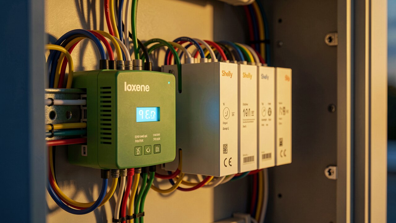
The core formula is Qc = P × (tanφ₁ − tanφ₂), where P is the active power in kW, φ₁ is the phase angle of your measured power factor, and φ₂ the angle of your target. Example with round numbers: at 100 kW and a measured cosφ of 0.80 (tanφ = 0.75), targeting cosφ 0.95 (tanφ = 0.329), you need 100 × (0.75 − 0.329) ≈ 42 kvar. Size against the typical operating load, not the annual peak — an oversized bank overcompensates at part load, pushes the network capacitive, and can be penalised in the same way as a poor inductive power factor. Base the calculation on measured data, never on nameplate ratings alone.
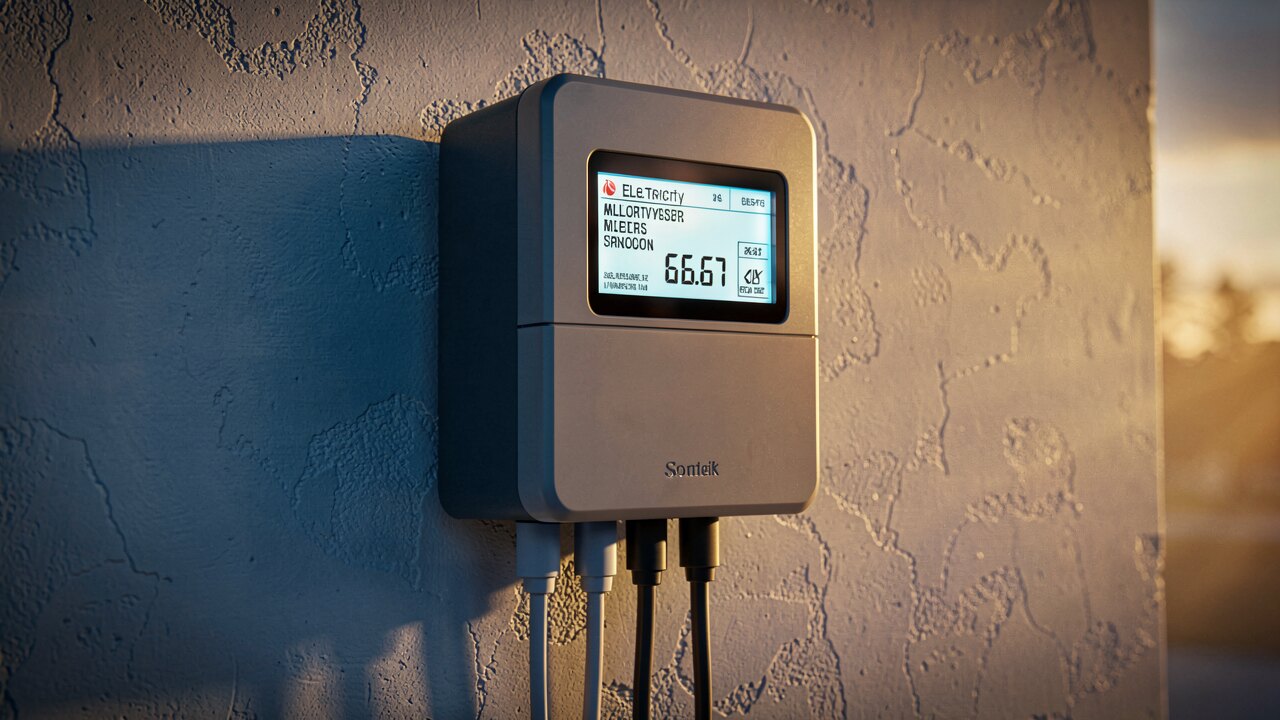
There is no universal legal figure — the target comes from your grid operator's or supplier's contract, so read it before you size anything. In practice most German network tariffs define a reactive-energy threshold around cosφ 0.90 to 0.95 and bill the reactive energy drawn beyond it. Planning to roughly cosφ 0.95 is the common compromise: it clears the usual billing threshold with margin, without the risk of tipping into capacitive territory during low-load periods such as nights, weekends, or shutdowns.

Capacitors and the supply transformer's inductance form a resonant circuit. If a harmonic from your VFDs, rectifiers, UPS units or LED drivers sits near that resonance, currents are amplified and capacitors, fuses and cables fail early. This is why the harmonic measurement is a planning step and not an afterthought. Where significant non-linear load exists, detuned (reactor-connected) banks are standard: a series reactor tunes the circuit below the lowest relevant harmonic — 7% detuning (tuned near 189 Hz in a 50 Hz network) is the common general-purpose choice, 5.67% and 14% are used for other harmonic profiles. Undetuned capacitors only belong on networks with genuinely low distortion. If distortion is severe, compensation alone is the wrong tool — a filter or active solution belongs in the plan.
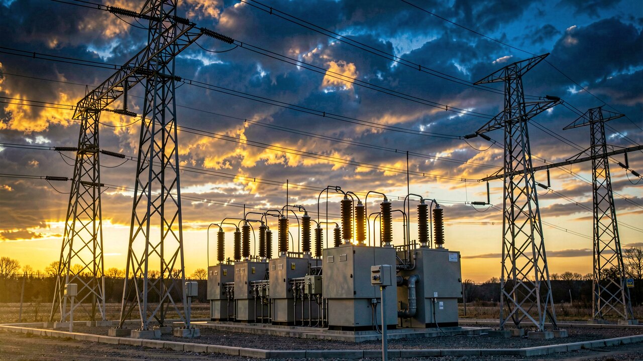
The total kvar is split into steps so the controller can follow the load. Smaller steps mean finer regulation and less power-factor hunting; too many steps raise cost and contactor wear. Common practice is a graded arrangement (for example 1:2:4) that produces many effective combinations from few steps. Switching technology follows the load's speed: contactor-switched steps are fine for slowly varying loads, but need a discharge interval before a capacitor can be re-energised. For fast, cyclic loads — welding, cranes, presses, lifts — thyristor-switched (dynamic) compensation responds within milliseconds and is the correct choice.
Place the bank where the reactive current actually flows and where the ambient temperature and ventilation suit the capacitors — heat is the dominant cause of premature capacitor ageing. Cables, fuses and switchgear must be rated above the nominal capacitor current, because capacitors draw harmonic current on top of the fundamental and carry a tolerance on their rated capacitance; follow the manufacturer's derating guidance rather than the nominal figure. The controller's current transformer must sit so it sees the total plant load including the capacitor bank itself — a misplaced CT is the single most common commissioning fault. Verify after energisation by re-measuring cosφ and distortion under real load, and plan periodic re-checks: capacitors lose capacitance as they age, and a plant whose load mix changes will drift away from its design point.