Leistungsfaktor = Power Factor: Definition, Formula and What It Costs You

"Leistungsfaktor" is simply the German word for power factor: the ratio of real power (kW) to apparent power (kVA) at your connection point. It tells you how much of the current your site draws is actually doing useful work — and how much is just circulating.
Power factor is real power P (kW, the part that turns into torque, heat or light) divided by apparent power S (kVA, what the cable and transformer must actually carry). PF = P / S, a dimensionless number between 0 and 1. A PF of 1.0 means every ampere is doing work. A PF of 0.7 means only 70 % of the transported power is useful — and, as a rule of thumb, roughly as much reactive power is flowing as real power. That reactive share still heats your cables, loads your transformer and is metered by many grid operators.
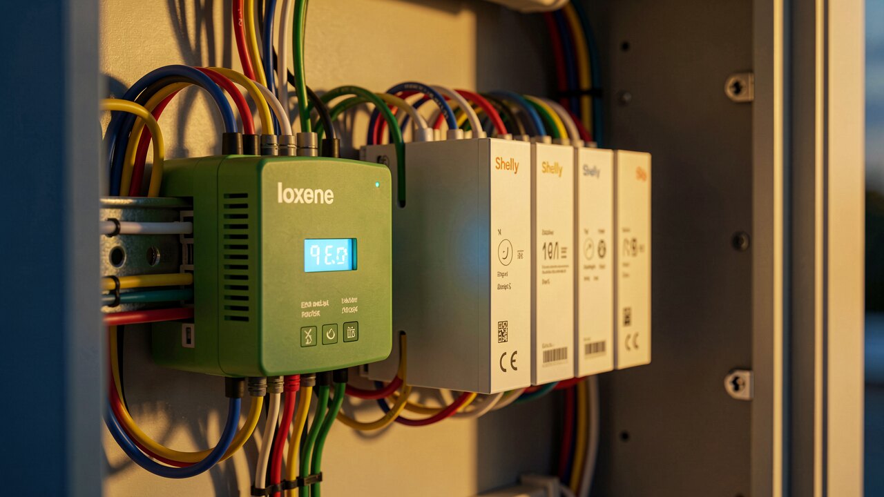
1) Read real power P in kW from your meter or load-profile data. 2) Get apparent power S in kVA — single-phase S = U · I, three-phase S = √3 · U · I (line-to-line voltage). 3) Divide: PF = P / S. If you know the reactive power Q (kvar) instead, use the power triangle: S² = P² + Q², so Q = √(S² − P²) and PF = P / √(P² + Q²). For a clean sinusoidal supply with linear loads, PF equals cos φ, the cosine of the phase angle between voltage and current.
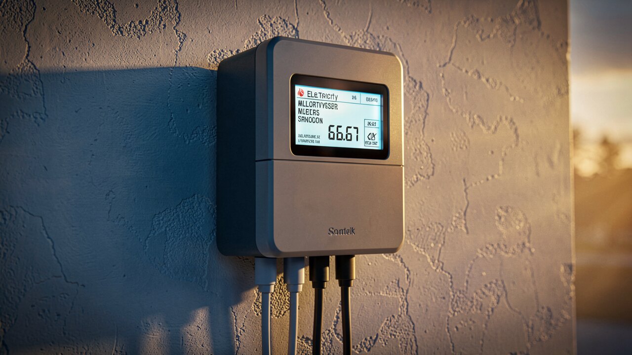
cos φ only describes the phase shift (displacement). With modern non-linear loads — variable-speed drives, LED drivers, switch-mode power supplies, rectifiers — current is also distorted by harmonics. True power factor = displacement factor (cos φ) × distortion factor, so it can be noticeably lower than the cos φ your controller displays. If your site is drive- or electronics-heavy, measure true PF and total harmonic distortion, not just cos φ; capacitor banks alone will not fix a distortion problem, and can even resonate with it.

Inductive loads — motors, transformers, welders, chokes, fluorescent ballasts — make the current lag the voltage: lagging PF, the classic industrial case. Capacitive loads and long lightly loaded cables, and PV inverters set to a capacitive setpoint, make current lead: leading PF, which is increasingly common at sites with large PV arrays at light load. Both are penalised the same way by the network: extra current for the same useful kW. The fix depends on the sign — capacitors for lagging, reactor/detuned settings or inverter reactive setpoints for leading.
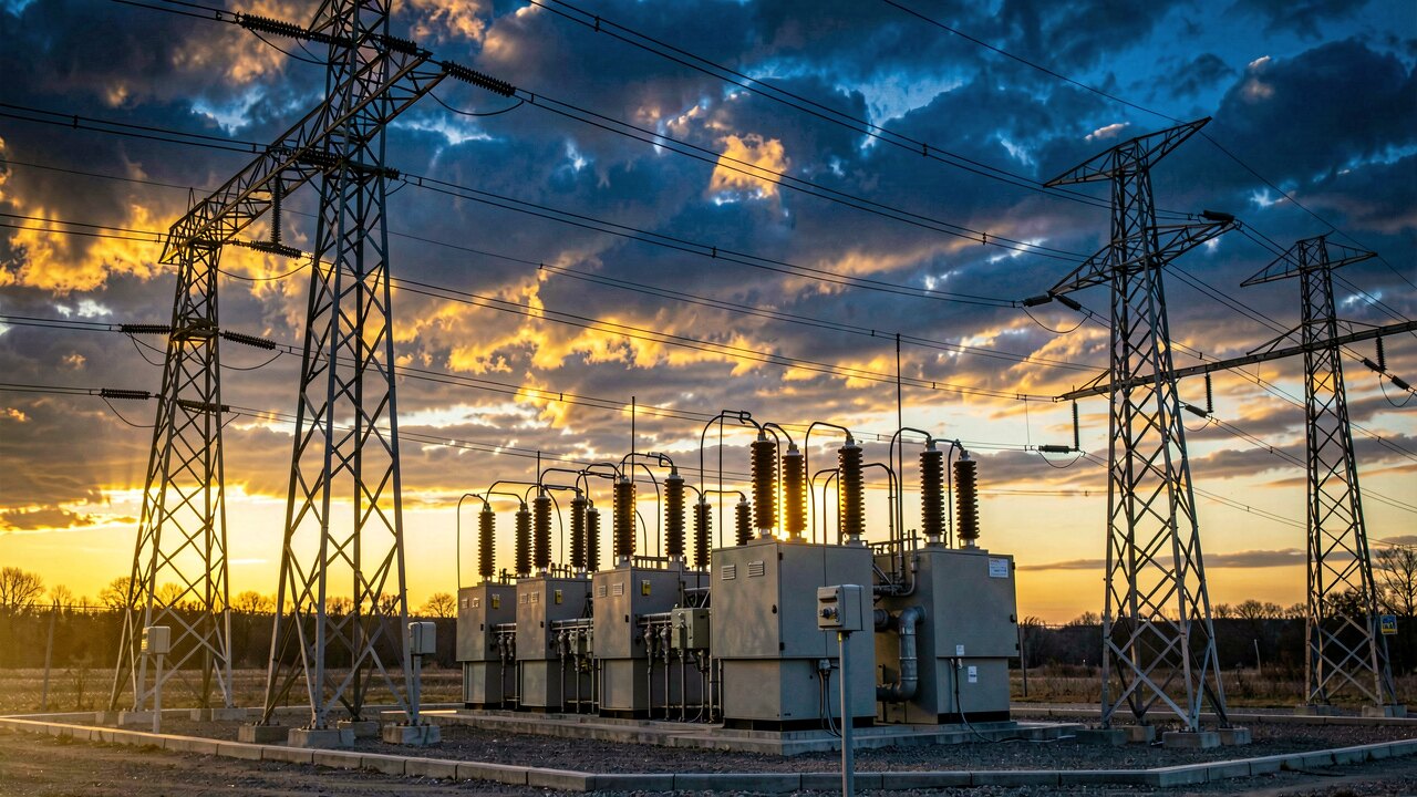
Many European grid operators expect industrial connections to stay near unity, commonly around cos φ 0.9 or better, and bill reactive energy above the allowance — check your own connection contract and network operator's technical terms for the exact value, as it varies by operator and voltage level. Typical measures: switched or automatically regulated capacitor banks (with detuned reactors if harmonics are present), reactive power control via PV or battery inverters, correctly sized rather than oversized motors, and avoiding long no-load running of large drives.
A poor power factor raises current, and losses rise with the square of current. For customers metered on the low-voltage side of their own transformer, German grid operators traditionally added a flat loss surcharge of typically 2–3 % for transformer losses. The German regulator's decision BK6-13-042 on the network use and supplier framework contract (electricity) no longer permits that blanket approach. Transformer losses split into no-load (core) losses, which run whenever the unit is energised, and load losses, which depend on the current actually drawn — so they can be calculated individually from the equipment ratings plus the customer's load-profile data, instead of estimated by a flat percentage.